Hacking a Datalogic Magellan 1100i
Nothing very complicated but I want to share how to add a USB connector to a Datalogic Magellan 1100i barcode reader, for using it in keyboard mode.
Avertissement
I’m not responsible if your destroying your hardware!
But first, some context about why I did this. I recently join the french food cooperative La Chouette Coop [fr] located at Toulouse. When I joined the co-op I had in mind to do nothing computer-related. But as soon I said I was a developer, I was asked to join the IT group because they were looking for people with experiences in this domain. So I said « Why not? » and I discover they’re doing all they can to stay away from GAFAM and other companies who are a threat for our privacy.
The first project I did was to add a USB connector to a barcode reader without connector. An other person have already do some research and merge a USB cable lying around in a drawer to the barcode reader. But it was only powered and was not recognized by the computer where it was connected to. This is my starting point since the other person who did this has left to deal with something unrelated to this project.
After he tell me what he found and give me all the documents he have, I started searching and the solution was simple but not obvious.
The first thing to check is if the wiring is ok, all seems fine but the tricky part was to check the wiring for the cable in the barcode reader. With the correct tool I was able to easly open the part where the wire is connected to the barcode reader. I used a thin screwdriver and put it in the hole which I surrounded in red in the following picture.
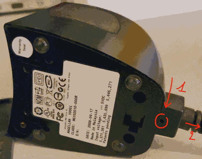
Normally you have to feel a slight pressure as if you were pressing on something (which you are). Keep pressing with one hand (like indicaded with the arrow number 1) and with your other hand pull the cable out of the barcode reader (like indidcated with the arrow number 2).
Now you should have something like this (If not, what have you done? ^^):
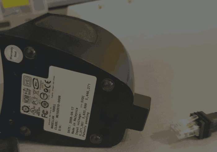
In the image above we can see a connector who looks like an RJ45 connector but it’s not. Based on my research this would be an RJ50-10 connector.
Now make a mapping from the color linked to the pineout explained in the barcode reader official documentation pages 175 and 176.
You can selected the pineout you want, it’s not important for this part but keep in mind that some cables are not connected to the connector.
Here is the wiring mapping of my barecode reader (maybe it diferent for your):
RJ50-10 connector          Color code
1  <----------------------> Not wired
2  <----------------------> Green
3  <----------------------> Not wired
4  <----------------------> Blue
5  <----------------------> Unknown
6  <----------------------> Grey
7  <----------------------> Unknown
8  <----------------------> Yellow
9  <----------------------> Black
10 <----------------------> Unknown
Yes, some are unknown because I only check the colors for the
USB, USB Keyboard & USB COM pineout that we’re going to use.
Now we know what color corresponds to which RJ50-10 connector pin, we can prepare our two cables for the merge.
You can found the USB cable color mapping on the internet easly but here it is:
Black (GND)
Red (VIN)
White (D-)
Green (D+)
After that, just merge the two cables with the following mapping:
Barcode reader wire     USB wire
Black  <--------------> Black
Yellow <--------------> Red
Blue   <--------------> White
Grey   <--------------> Green
Follow the kernel ring buffer with the command dmesg -w and you will see
something like this if your merge is correct:
[53441.314468] usb 2-1.1: new full-speed USB device number 29 using ehci-pci
[53441.484190] usb 2-1.1: New USB device found, idVendor=05f9, idProduct=4601, bcdDevice=18.71
[53441.484195] usb 2-1.1: New USB device strings: Mfr=1, Product=2, SerialNumber=3
[53441.484198] usb 2-1.1: Product: Point of Sale Handable Scanner
[53441.484200] usb 2-1.1: Manufacturer: PSC Inc.
[53441.484202] usb 2-1.1: SerialNumber: C10100756
Why if? The thing is, at start, I stayed too long on the mapping done by me colleague and it wasn’t working. The solution was simply to inverse the white and the green wire of the USB cable like the mapping above and everthing works as desired.
Anyway. Now you can configure your barecode reader normally with the mode you want. I hope you’ll find this useful.